Magnets play a critical role in activating reed switches, with their material, shape, and magnetic properties directly influencing sensor performance. This guide explores various magnet types, such as AlNiCo, rare earth, and hard ferrite, highlighting their specifications, applications, and handling considerations to help engineers select the optimal magnet for reliable and efficient sensor integration.
If there are particular areas you need help with, feel free to skip to any of the following sections:
- Magnet Specifications
- Magnet Materials Information
- AlNiCo Magnets
- Rare Earth Magnets
- Hard Ferrite Magnets
- Magnet Handling
- Magnetisation Examples
Magnets and Their Specifications
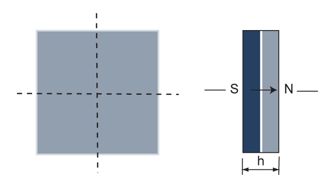
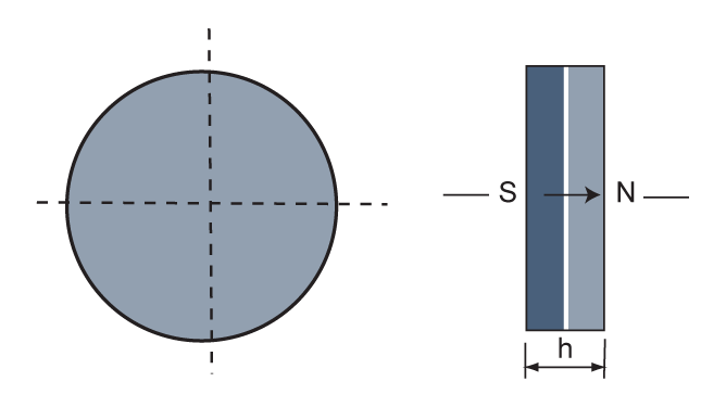
Magnets are available in multiple specifications on the market. Almost all dimensions and geometries can be realised. To activate the Reed switch a magnet (magnet
field) is needed. The different magnet materials have either more positive or negative specifications, depending on the dimensions and geometries as well as on the
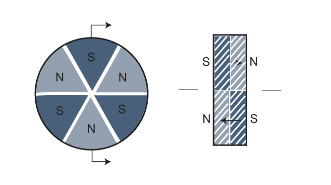
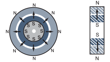
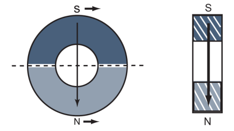
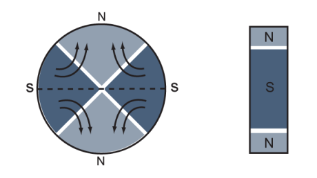
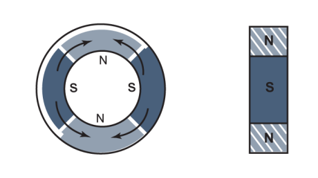
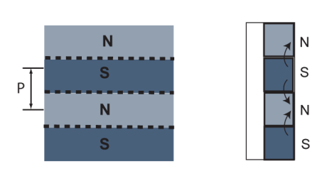
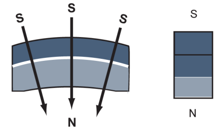
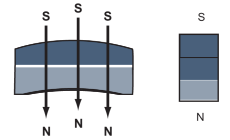
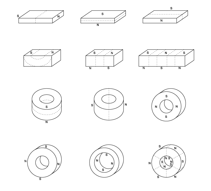
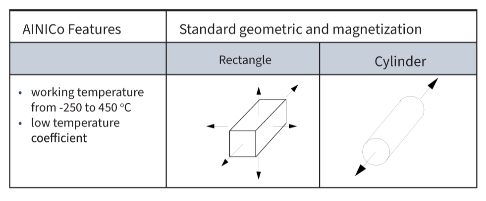
environment. The most preferred and used forms are cylinders, rectangles, and rings. Depending on the different requirements, magnets can be magnetised in many
different ways (figure #1).
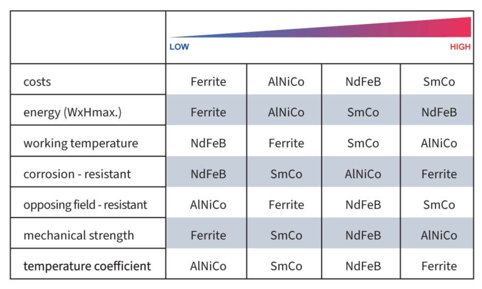
Furthermore, each magnet material has a different magnetic force as well as a different flux density. In addition to dimension and material, other factors exist that define
the energy of a magnet. These are mounting position, environment and other magnetic fields which influence the interaction between reed sensor/switch and magnet. In
applications where a magnet is used to activate a Reed sensor/switch, the environmental temperature needs to be considered (in the application as well as in storage). High temperatures can cause irreversible damage (so-called Curie temperature) and will have a heavy impact on the magnetic force and long-term stability. AlNiCo magnets are best suited for applications up to 450°C.
Magnet Materials Information
Magnets have reversible and irreversible demagnetisation specifications. Be especially careful with shock, vibration, strong and close external magnetic fields as well as high temperatures. All these factors influence the magnetic force and long-term stability at different intensities. Preferably, the magnet is mounted on the moving part of the application. Professional tuning of magnet and reed switch can improve the
functionality of the whole sensor-magnet system.
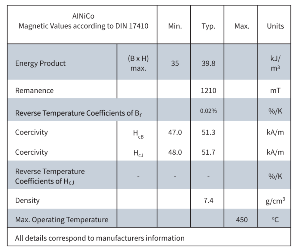
AlNiCo (Aluminium Nickel Cobalt) Magnets
Raw materials for AlNiCo magnets are aluminium, nickel, cobalt, iron and titanium. AlNiCo magnets are produced in a sintering–casting procedure. The hard material needs to be processed by grinding to be cost-effective. Due to its specifications, the best dimension is a markedly longer length than its diameter. In combination with Reed sensors/switches we recommend a length/diameter ratio of more than 4. AlNiCo magnets have excellent temperature stability. Cylindrical AlNiCo magnets can be used with all Standex Detect Reed sensors/switches without any problems.
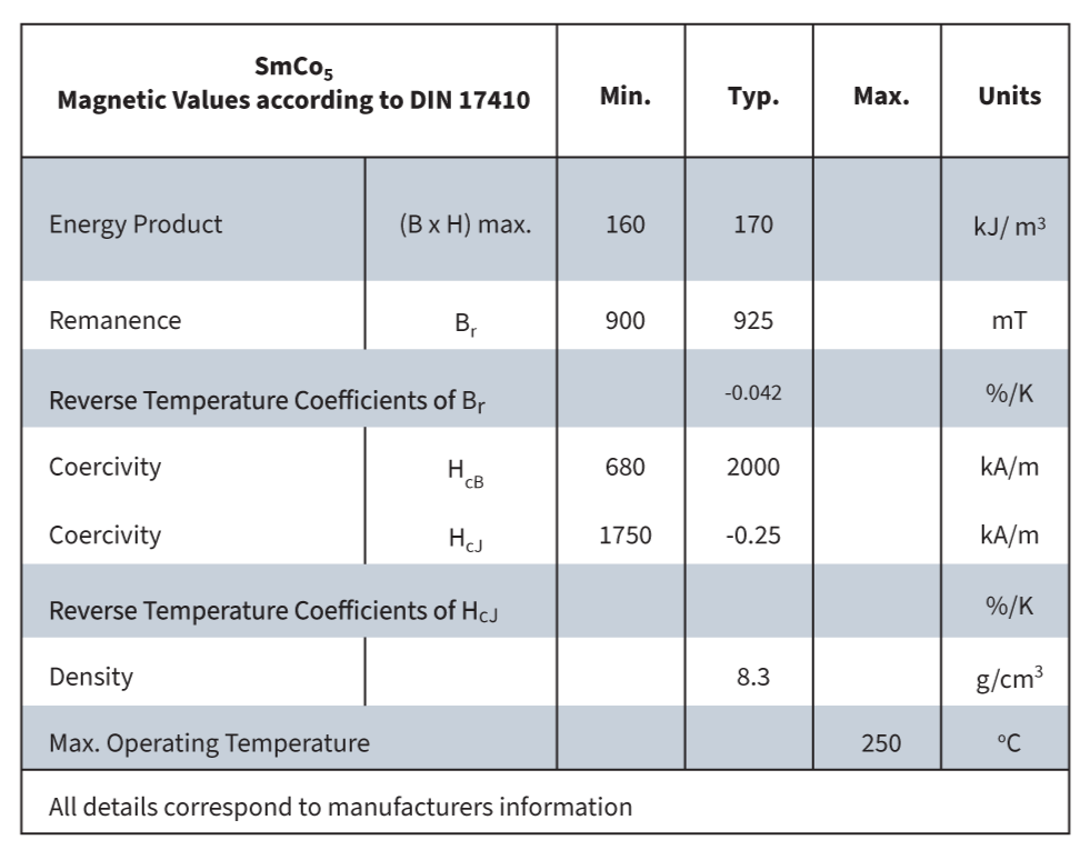
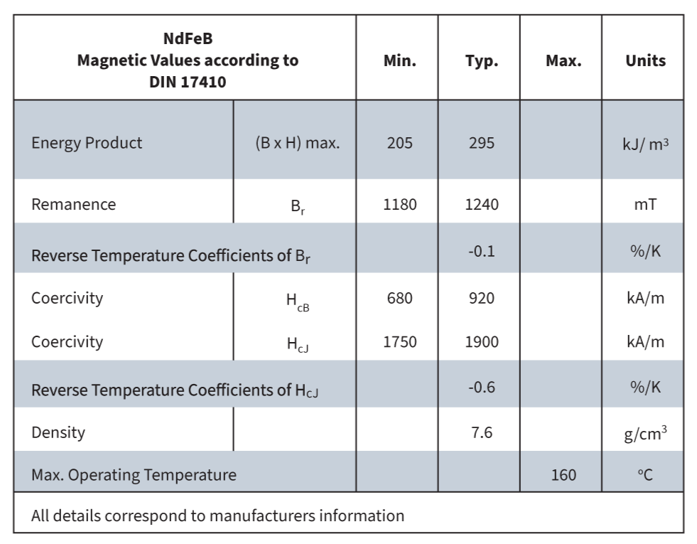
Rare Earth Magnets (NdFeB & SmCo)
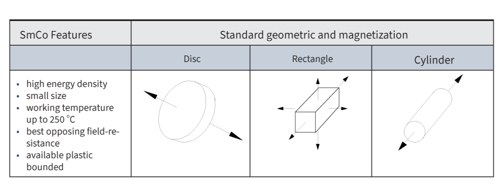

Rare earth magnets like SmCo and NdFeB have the highest energy density per volume and weight and also the best demagnetisation resistance. Below, we compare other magnets with the same energy:
- Hard Ferrite = Volumes 6 cm3
- AlNiCo = Volumes 4 cm3
- SmCo = Volumes 1 cm3
- NdFeB = Volumes 0.5 cm3
Both magnets are produced by sintering and can only be processed by grinding, due to the strength and brittleness of the material. The temperature range goes up to +250°C. Very small magnets can be produced. Disadvantages are the high raw material prices and the limited availability of special alloys.
The supply of different geometries, sizes and magnetisation allows many creative combinations of Reed sensor/switch and magnet and helps to find the best functionality of the sensor-magnet system for each application.
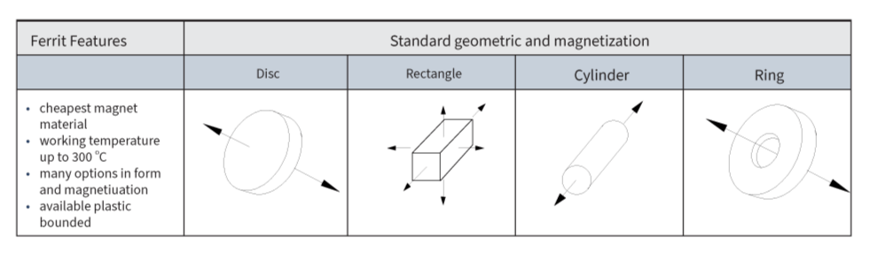
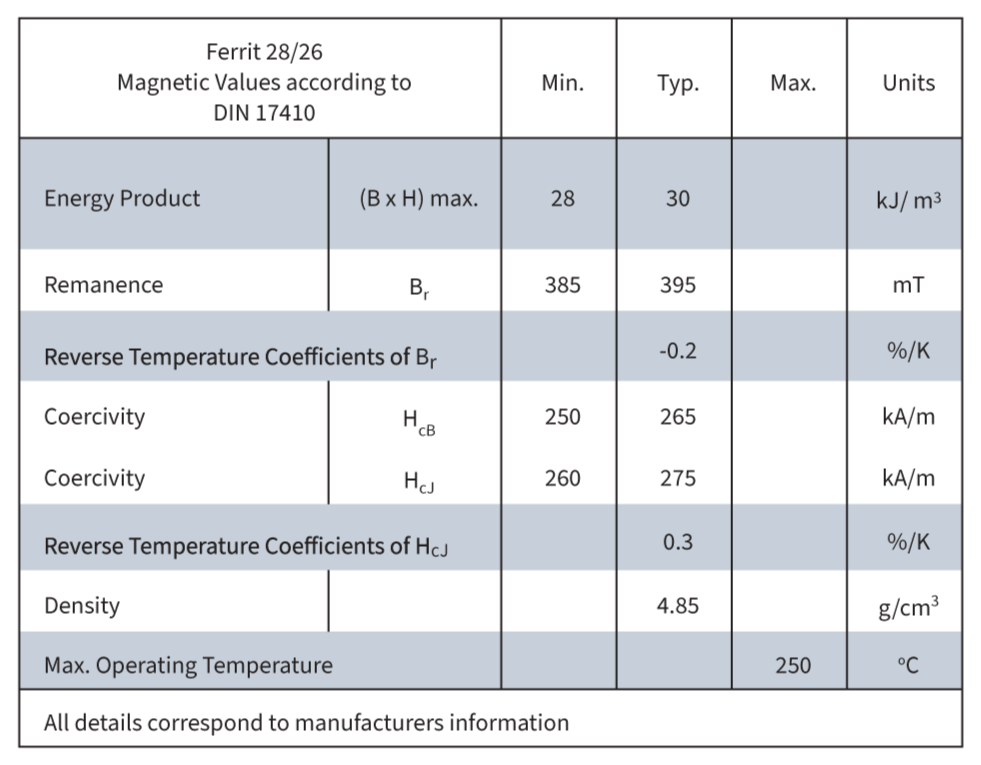
Hard Ferrite Magnets
Hard ferrite magnets are produced with iron oxide and barium or strontium oxide. The raw materials are mixed together and normally pre-sintered to generate the magnetic phase. The pre-sintered mixture then gets crushed. The resulting powder gets pressed together (wet or dry) either in a magnetic field (an-isotropic) or without a magnetic field (isotropic) and, in the end, sintered. Processing is only possible by grinding. Due to the low cost of the raw material, hard ferrite magnets are the cheapest magnet type in the current supply of magnets. Ferrites have a very good electrical insulation effect and are hard to demagnetise even in strong external magnetic fields. Corrosion tendency is low. Preferred shapes are long and thin, but round forms are also easy
to produce. Disadvantages are the high breakability and the low tensile strength. The strength and brittleness of hard ferrites are similar to ceramics. Furthermore, the
temperature resistance is limited, and they have only a low energy-to-volume ratio.
Magnet Handling Guidelines
Magnets, especially high-strength rare-earth types, pose unique safety risks during handling and processing. To prevent injury, equipment damage, and fire hazards, it is essential to follow specific precautions. The guidelines below outline critical safety measures to ensure safe and responsible magnet use in industrial and laboratory environments.
- Risk of Skin Injury
- Strong magnetic forces can cause skin bruises. Maintain a safe distance between magnets and all ferromagnetic materials.
- Splinter Hazard
- High-energy magnet collisions may produce splinters. Always wear protective gloves and safety glasses.
- Fire Risk from Grinding Dust
- Grinding dust from rare-earth magnets is spontaneously flammable. Always grind with water.
- Magnet collisions can cause sparks. Do not handle or process magnets in explosive (EX) environments.
- Electromagnetic Interference
- Strong magnetic fields can disrupt electronic devices and data storage. Keep magnets away from pacemakers, navigation tools, diskettes, and circuit boards.
- Air Cargo Regulations
- Special declarations may be required for air transport of magnets.
- Magnetic Force Reduction
- Radioactivity and joining like poles can weaken magnetic strength.
- Temperature Limits
- Do not exceed the maximum defined operating temperature of the magnet.